The "Works Every Time" method for car Automotive Driving Light wiring.

image

I frequently see wiring diagrams for Driving Lights that just don’t work in many cars.

Toyota nearly always and Nissan often use a what is known as “switched earth” wiring for their headlights. They do this so that each headlight can have it’s own 12v supply and fuse, meaning in the event of a problem, you only lose one light.

In a switched earth headlight, assuming you are using a H4 bulb with 3 pins (very common) the power is switched twice. +12V is fed through a relay or switch to the common pin, and then either one of the other pins (one for High, one for Low) is alternately connected to ground through another relay or switch. If you go looking for +12V to power your driving lights or their relay in this system, you wont find it easily.

A far easier method is to always wire the trigger for your relay ACROSS the high beam bulb circuit, instead of from +12v to ground. This means that regardless of the vehicle wiring, positive or negative switched, the driving light wiring is the same.

There are several other benefits to wiring in this manner.

a) It works with either positive of negative switched headlights

b) It avoids problems with the relay not dropping out. The high beam indicator inside the car can trickle enough power through to not let the driving lights drop out. It takes about 8-9V to trigger a 12V relay, but only about 4V to hold it in.

c) It avoids problems with the relay not dropping out due to a poor contact on the headlight connection. This common fault can setup a circuit through the other filaments and cause enough voltage to be present on the high beam filament to hold the relay open. This voltage is far less across the filament than in relation to ground.

image

image

So how do you wire it?

It’s easy really. I have gone with text, as many people have trouble with electrical diagrams.

Power CCT (Heavy wire)
Battery – Fuse – Relay (Pin 87) – Relay (Pin 30) – Driving Lights – Chassis (Ground)

Switch CCT (Light wire)
Headlight Common Pin – Switch – Relay (Pin 85) – Relay (Pin 86) – Headlight High Beam Pin

Simply tap into the headlight wires / pins with vampire taps.

Presto – I guarantee it will work.

If you don’t have H4 bulbs, even easier, simply go straight across your high beam bulb wires for the trigger.

ABS Diagnostic for you 100 Series Landcruiser

  • Connect terminals Tc and E1 of Check Connector (in engine bay) and remove the short pin (normally inserted in bottom right corner).
  • Turn the ignition switch on.
  • Depress the brake pedal 8 or more times within 5 secs.
  • You can now read any DTCs on the ABS Warning Light, but if everything is OK, you get the Normal Code (on-off blink with 0.25 sec intervals).
  • Revert Check Connector to normal.

Codes

  • 11=ABS Solenoid Relay Open or Short Circuit
  • 31=Right Front Wheel Speed Sensor Signal Malfunction
  • 32=Left Front Wheel Speed Sensor Signal Malfunction
  • 41=Low Battery Voltage or Open IG1 Circuit
  • 49=Brake-light Switch Open Circuit
  • 56=Accumulator Low Pressure Malfunction

IMG_1693s

IMG_1694s

IMG_1695s

Are the MTZ’s tough enough?

Whilst my Mickey Thompson MTZ’s are on the best on-road tyre, they are pretty damn good offroad.

Their wear rate has been a little high so far, and they are vague on the bitumen, tracking and wandering a bit. It is improving as they wear down, but s straight line tyre they are not.

Here is a pic of them working over nasty stuff, mostly at 17PSI with a 100 Series Landcruiser and gear on top.

P5310092

Toyota Landcruiser 100 Series ‘98-‘04 Temp Gauge Mod


Centred

It’s fairly common knowledge that the OEM Toyota temperature gauge has a large “dead spot” in the centre of it’s range. This spot is deliberately engineered to reduce the apparent fluctuations and make the car appear to run at a constant temperature unless there is a significant problem. This works fine for most, but those of us that like to know what’s going on sooner rather than later, demand a little more detail. Many people fit an aftermarket gauge somewhere in the car, I figure, if the factory gauge is already there and can be made accurate, use it.

One of the clever guys over at ih8mud figured out the circuit and how to modify it in his 80 series. He deserves full credit for the original article and all the work behind it. There is also a version for the Toyota Surf and Hilux. 

The gauge circuit in my ‘98 HZJ105R was a little different to the earlier 80 Series, so I had to re-do the calibration to suit.
I also had the opportunity to see the inside of a post ‘04 update dash, and unfortunately, it’s quite different. Someone will need to do their own testing and research on that one.

I bench tested various setups and found the following as a simple description.

test rig     
Bench testing w/ Digital Thermometer

temp test rig
Heating the sender unit in vegetable oil

wiring
Mmm, wiring.

components
Resistors and Diode

We do not change the 15 Ohm resistor.

There are 2 components we replace, a resistor and a diode. The diode is what makes the gauge “non-linear”. Rather than explaining what they do in a wheatstone bridge, I’ll explain their effect on the gauge.

The gauge with no input actually sits in the middle of the scale. The 75 Ohm resistor we change “sets” what temperature the middle of the scale is to be. A lower value resistor sets it higher, a higher value resistor sets the scale lower. I found the following:

  • 100 Ohms = 90c
  • 120Ohms = 85c
  • 82 Ohms = 95c

centering test
Gauge w/ no input – centres on scale.

The small glass diode gives a non-linear (dead spot) in the needle’s range. We replace this diode with a resistor to make the gauge react “normally”. The value of this resistor determines the “range” of the gauge. A lower value resistor gives large movement for small temp changes, a high value resistor gives less movement. Using no resistor with a 90C centre means the gauge hits the red at 94.5C – a little too low.

centering - no damping
No Damping Resistor – large deflection

I found a value of 82 Ohms gives a good range with 115C touching the Red, 125C middle of the red and 65C touching the Cold. Properly mixed coolant boils at approximately 125C – 128C at 14PSI, and I’m not interested in below 65C, as the engine is not yet at operating temp.

This combination gives me the best combination of “”operating near the middle” and “enough movement to see what’s happening”. With the above detail you can adjust your own numbers if you wish.

The 100 Ohm resistor gets hotter as engine temps increase and will possibly exceed 1 watt. I recommend a 2 watt resistor. 5 Watt is very large and may not fit or be too heavy. The temp sender resistance decreases with heat, increasing current through the resistor.
The 82 Ohm resistor dissipates less than 1/4 watt, but I used a 1/2 watt to be safe.


  Original Modified
130 a130 b130
120 b120 b120
110 a110 b110
100 a100 b100
90 a90 b90
80 a80 b80
70 a70 b70
60 a60 b60
50 a50 b55


You will need the following

  • OEM ‘98-‘04 Landcruiser Dash
  • 2 watt, 100 Ohm resistor
  • 1/2 watt, 82 Ohm resistor. 


Remove the gauge pod from car and disassemble. Be careful removing it from the car – there are 4 screws and 2 bolts. The bolts are captive and hold the plug connections, but need to be unwound a lot to release the plugs. P4040008
Remove the temperature / oil pressure gauge assembly. P4040009
Remove the 75 Ohm resistor and Diode. components
Replace the 75 Ohm resistor with a 100Ohm and the Diode with a 82 Ohm. P4040001


Detailed pics below (5C steps)

  Original Modified
130 a130 b130
125 a125 b125
120 b120 b120
115 b110 b115
110 a110 b110
105 a105 b105
100 a100 b100
95 a95 b95
90 a90 b90
85 a85 b85
80 a80 b80
75 a75 b75
70 a70 b70
65 a65 b65
60 a60 b60
55 a55 b55
50 a50

Tuning and Understanding your Toyota Viscous Fan Clutch

Landcruiser or Hilux overheating? Your factory fan clutch is probably under-filled and incorrectly set from factory. Fix this first and you may save a lot of time chasing issues.

(4 Runner or Tacoma in the USA)

P3280006 - Copy

The stock Toyota cooling system can sometimes be somewhat marginal. The suspicion for this falls on every component and modification in the system.

  • Radiator (Size / Efficiency)
  • Thermostat (Brand / Effectiveness)
  • Water Pump (Flow, Cavitation)
  • Radiator Cap (Quality, Pressure, Leaks, Recovery)
  • Coolant (Freezing / Boiling points, Specific heat, Anti-corrosion)
  • Hoses (Restriction)
  • Engine Type (Diesel / Turbo / Petrol)
  • Engine Load / Modifications (Diving style, load on vehicle, Mods)
  • Gearbox (Auto Cooling, Slipping)
  • Airflow (Obstructions / Restrictions In / Out, Forced / Natural)
  • Ambient Operating Environment (Temp, Altitude, Terrain)
  • Shrouds (Closeness to Fan, Leaks, gaps between radiators)
  • Fan (Size / Pitch / Airflow)
  • Fan Clutch (Lockup Temp / Stages / % Slip)
  • Temperature Gauge (Damping / Accuracy)
  • Bullbars / Winches / Lights / Antenna’s / Plates / Screens

Ask anyone and they’ll start listing random items from the list above that they have seen before or are suspicious of. It would appear that the issue is simply that the system is marginal in certain areas, and several small changes may be enough to tip it over the limit.

The end goal of a cooling system is to transfer heat to the surrounding air. All the other components are only there to allow this transfer to occur in some improved fashion. There are plenty of air cooled motors in existence that do not have these complexities, and they too may be subject to overheating.

It would appear that Mr Toyota VERY closely engineers his vehicles, with many parts sharing multiple purposes, and many many tradeoffs being made. This is good engineering, but it means that small changes may have many unintended impacts. Despite this, it appears the Landcruiser and Hilux are intended to be frequently modified. There are many attachment points, and the OEM design has many dealer supported aftermarket options that are not from the Toyota factory.

If all the basic checks have been performed on the cooling system – no leaks, nothing obviously blocked, quick warm up, infrequent overheating except under specific circumstances, then it is a fair bet that the overall system is simply marginal. In this case, a dramatic increase in specific areas may yield a significant benefit.

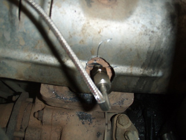
In my case the overheating was limited to situations with a pre-turbo EGT in excess of 550C. This equated to High Load or High Speed driving. Despite expectations, off-road steep terrain (sand excluded) does not yield high EGT’s. Mountain Ranges, Large Trailers, Roof Racks, High Speed or Deep Sand all would yield high EGT’s and therefore problems.

I have measured many temperature points around the engine bay, and spent some time listening to the engagement and disengagement of the fan. All this yielded much confusion rather than understanding.

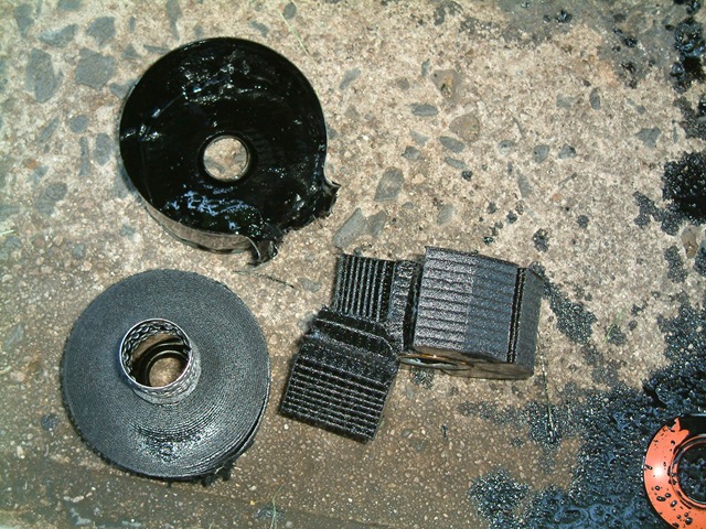
I replaced most components, some twice. It was during this that I had time to closely examine and understand the Toyota Viscous Fan Clutch. Possibly more than any other component, this is the key item in the cooling system. It is this that creates the airflow, not vehicle forward speed. Without airflow, the radiator is not effective. My experience was very similar  in a Toyota Surf I had owned previously. It is common knowledge that additional Silicon Fluid will often improve these units. What is not common knowledge is:

  • Brand new OEM clutches appear to be under-filled
  • They can be adjusted where they engage
  • There are 4 separate engagement stages
  • Testing cannot be done one the bench. The device requires centrifugal force to operate.

Credit goes to Frank for his guide on how to split and refill the fan clutch. I am just explaining the operation in further detail.

It must be remembered that these types of fluid couplings always have some slip. They may slip by 98% (free spin) or 5% (coupled), but there is always slip. It is difficult to test the slip in any simple manner, and impossible to bench test. Therefore a fan that appears to be engaging and disengaging successfully, may in fact be slipping at 50%, significantly reducing maximum airflow. Worse, the slip will be only happen at high RPM and maximum load.

The key points are that there are 4 operating stages, and that there is not enough fluid to couple the system adequately.

This is why so many people report success with simply adding more fluid. Adding fluid means that when the system is operating with the valve fully open, the rings are full of silicon fluid, and not partly full. The only drive is through the fluid, so insufficient fluid will reduce maximum coupling ability. There was clearly not enough fluid in the unit to fill all the rings to the depth of the final valve.

The factory engagement points are also quite high. This reduces noise and fuel consumption, but also means maximum engagement doesn’t occur until the air temp is around 95C. Engine coolant temperature will always be higher than air temperature.

This was all tested with a Digital Thermometer and a water bath on the stove.
The water was heated and cooled and the valve set points noted as it moved.

P3230007

Temperature Set Points (all at 1/2 open)

Stage Original Temp Adjusted Temp
Closed 50 40
Stage 1 55 45
Stage 2 85 75
Stage 3 95 85

Pictures of operation:

Fan Clutch P3280006 - Copy
The 2 halves opened BlueFanClutchApart[1]
The “drive disc” spins freely in the housing except for the silicon fluid. P3230019
The “drive disc” and the “front half” share these closely spaced rings. It is these rings, and the silicon fluid in the gaps between them that couple the system together.The inner ring is taller than the others.

The oil is slowly thrown to the outside of the system by centrifugal force.

P3230004 P3230011
The fluid is rated at 10000 Cst – Centistokes – a measure of viscosity P3230009
The valve that controls where the fluid flows. It operates over 4 stages:0) Closed
A) Some oil to some rings
B) Some oil to all rings
C) Maximum oil to all of rings

This is why it seems to be more than engaged / disengaged.

P3230005 - Copy - Copy
The temperature sensing Bi-Metal spring on the front face that controls the valve. BlueFanClutchthermosideup
The reservoir behind the valve disc in the front half where the fluid is stored. When operating it is held here by centrifugal force, and pumped here by the slipping “drive disc” P3230012
The “vanes” on the edge of the drive disc in the rear half that pump the fluid forward to the outer channel for return to the reservoir. Some slip is required to allow the pumping to occur.The slots in the back of the disc pump the fluid from behind the disc to the edges, and then to the channel at the front.

The rear of the disc is not used for coupling.

P3230019
P3230011
The wedge shaped guides and small holes in the front half that collect the fluid from the outer channel and push it back into the reservoir. P3230002
Adding Fluid P3230008
Adjust the valve set point by loosening the 2 screws and rotating the disc.
The outer valve should be 1/2 open at about 45C for Australia. (US quotes 35C). Air temp will always be less than engine water temp.
P3230001
Getting the fluid level right is a little difficult and involves some guesswork.The minimum amount required is enough to fill the entire outer rim past the depth of the fins in both halves, this fully couples the unit.

The maximum amount is when the reservoir in the front is full and overflows through the central hole. Not so simple though, as full is controlled by centrifugal force, so when operating it fills the “outside” of the reservoir, not the bottom.

Luckily there is a fair tolerance between the two. Overfull will couple the fan all the time.

Mine took 1.5 tubes of fluid in addition to the factory fill to stay a few mm below the level of the valve disc.

P3230014

Winch Mount Testing and Breaking Rope

I decided that my home made winch mount IMG_3804needed to be tested so I could trust it somewhat. I see from some of the conversations I am not the only one with doubts. The mount performed perfectly, although he synthetic winch rope broke.

The tests were all done on the first layer of the drum to give maximum tension. This also places additional load on the mount due to the increased height adding leverage.

Test 1 – Drag Car on Dirt (Wheels Locked)- Passed

Test 2 – Drag Car on Dirt Up Hill (Wheels Locked) – Passed

Test 3 – Drag Car on Bitumen (Wheels Locked) – Passed

Test 4 – Drag 2 Cars Uphill on Dirt (Wheels Locked) – Rope Failed

I believe the rope failed due to 3 factors

  1. The Technora fibre is wearing noticeably more than the Amsteel Blue. I have read that the high temp materials are less abrasion resistant.
  2. The fairlead internal radius is too sharp compared to the external radius. The radius should be 4x the diameter of the rope.
  3. The fairlead sits approx 3/4 up the height of the winch, giving a fair bend to the rope as it goes over the fairlead and down the bottom of the drum. Rope rated at 13,700lb loses strength when bent. The tighter the radius, the greater the strength loss. The numbers are hard, as it depends on the diameter or the rope, and it’s construction. 12 Strand is a good construction for bending.

I am surprised a 9500lb winch can break a 13,700lb rope.

At no point did the mount appear to bend excessively, or sustain any visible damage. There was NO permanent twist.

The fairlead mount also suffered no damage, and the rope was spliced back together easily.

I was surprised at the amount of spring in the rope, you can see it coiled up under the tree where it ended up.

 IMG_3798 IMG_3799 IMG_3800 IMG_3802 IMG_3803 P8030027 P8030026

4WD Winch without the Weight

I wanted to fit a winch P4260063to my ’98 HZJ105 without wearing a huge  weight penalty, or spending too much money. That ruled out walking into ARB and handing over the Credit Card for a new Bullbar and Warn. It meant I had to DIY this little exercise.

I wanted to keep the weight down, so decided a 9500lb was smaller and lighter than a 12,000lb. If I needed more pulling power, I would use a pulley block.

After reading the SA 4WD Winch Review, and getting a good deal, I bought a 9500lb Ironman Winch for $625 w/ 3yrs warranty. They are claimed to be waterproof and come with what I needed. I would have preferred a Premier winch due to the brake not being in the drum making it more suited to synthetic rope, but it was out of my price range. I would really have preferred a hydraulic Milemarker, but that was really really out of my price range, especially when I factored in questions around power steering pump flow rates.

After using steel cable and hating it, synthetic winch rope was a requirement. I figured 100ft (28M) of 5/16″ (8mm) rated at 13,700LB breaking strain would do. Less rope on the drum keeps the winch closer to it’s rated pulling force. I specifically bought their “Hybrid” line, where the first 25ft is a Technora based rope, and the rest is Amsteel Blue. The Technora is more temperature stable for use on winches with a brake inside the drum. I bought mine from www.cseoffroad.com, along with the alloy fairlead, rope protector and safety thimble. The alloy fairlead was a free bonus at the time. I also grabbed 100ft (28M) of 3/8″ (10mm) Amsteel Blue winch extension rated at 19,600lb breaking strain. The separate extension allows the flexibility of simply extending the pull, connecting two different points, putting a winch block in between the two etc. You need the thicker rope size if you are going to use a winch block, as it will double the pulling force – 9500×2 = 19,000lb.

The next item was a mount. Other mounts I have seen use 6mm steel plate in various arrangements. I settled for the thickest and strongest alloy channel I could get – 8.4mm x 6.8mm tempered alloy. It doesn’t have a rated “strength” in this configuration, especially after I chopped it up to get the winch to fit. I can say that in a pull to stall test, the rope snapped before the winch stalled, and the mount, while having a slight twist, suffered no permanent deformation. The winch is in an ideal position, directly between the chassis rails, very low, and as far back as possible. The mount acts to protect the radiator from sticks etc.

The fairlead I mounted into the bullbar with 20x heavy gauge rivets. Whilst I am not that confident as to their strength, in shear the steel pins combined with the tight fit should be very strong. At a 45deg pull they will be in both tension and shear, a less desirable situation. The alloy bar mounts are particularly weak in a sideways direction, so I think I’ll be avoiding heavy angled pulls. The fairlead needed to have it’s inside edge rounded a lot, as the winch sits quite low in relation to the bar.

Finally it was just a matter of the control box hidden inside the bar, the wiring and lockout switches. I recommend the lockout switches be waterproofed underneath with silicon, and rubber caps fitted (I used rubber “feet”). Water pulls inside them and the copper contacts stop working.The winch is wired with a switch to each AGM battery, letting me use either one, or both.

By dropping the steel cable and roller fairlead, using an alloy mount, not using a 12,000lb winch and keeping the alloy bar I have kept nearly 75KG off the front of the car. Just as importantly the weight is as low and far back as possible, something most winch bars don’t do. Whilst I accept it’s not as strong as a steel winch bar, it has passed every test I can throw at it so far.

Finally – it’s a whole lot cheaper than driving into ARB, and with Mickey T MTZ’s, twin Air Lockers and some lift, hopefully I won’t need to winch too often (yeah right).

Item Weight (KG)
Winch 21
Controller 3
Rope & Thimble 2
Fairlead 2
Mount 2.5
Total 29.2
Item Weight Saved (KG)
9500 vs 12000 10
Fairlead 4
Rope & Hook 8.5
Mount / Steel Bar 50
Total 72.5KG
The heaviest aluminium alloy channel I could find. It is also tempered (or so the guy said). 8.4mm base, 6.8mm walls. PB290026
Trimmed to fit winch and chassis rails with lower bull-bar mounts. I should have rounded the corners more to stop fatigue. PB290027
Winch fits nice and snug. PB290025
Alloy hawse fairlead mounted in the factory bar. Yeah I know, I know. If it snaps the rivets then I’ll do something sttronger. The alloy is 6mm checker-plate. The bar is not that strong, nor are the bar mounts. PC080067
Terminating the high temp Technora fibre. PC080072
Had to grind the allen key to fit the link on the rope. PC080069
All spooled up. Rope protector is the black bit.
I have a strong plastic / rubber  flap that covers this gap keeping grass and mud out.
PC080074
Pic when fitted. Yes, I suspect it may snag something one day. P4260062a
The lockout switches with waterproof covers. They don’t like water in them, and then don’t work. P4260062b
Internals of the waterproof control box. It’s zip-tied inside the bullbar. PB290028

Qld Transport supports Fuel Catalyst Scammers & Ripoffs

This just turned up with my rego renewal.

They are a scam, it’s so well documented I can’t even be bothered linking the hundreds of articles.

http://www.google.com/search?q=firepower+dans+data&rls=com.microsoft:*&ie=UTF-8&oe=UTF-8&startIndex=&startPage=1

Scammers, Charlatans, Scumbags, Liars, Theives, Con Artists, Rip Off Merchants, Fools and Money.

What next – Hyclone ads? I’ve got some magic fairy dust I would like to sell you…..

P7080001 P7080002 P7080003

1HZ Oil Analysis and Oil Changes

OK, oil analysis is neither simple nor my specialty. Here are the details from the last seven changes I have done, with an analysis at each one.

http://www.neuralfibre.com/paulfiles/Cruiser_Oils.xls

Oil Filter Pics Here

Technical info can be gleaned from links below or Google.

This analysis is not perfect or definitive. My motor is not factory and fuel system hasn’t been touched possibly ever (250,000km). I have changed multiple variables each time (oil, filter, driving style etc)

What I read into this analysis is

  1. I need to try 10,000KM filter changes, 5000 seems to be nowhere near capacity of the filter
  2. Mineral oil is fine at 15,000km, could go longer. 5000 is a total waste of time and money.
  3. Soot is the problem and it’s below 1micron. Very small. Hard to filter out.
  4. An additional filter *may* help, but would need analysis to prove if it’s effective.
  5. Although the factory Toyota filter appears to be far better constructed, it doesn’t perform any differently when changed at 5000KM, possibly worse from some of these numbers. I suspect if has far great capacity.
  6. Anyone that talks oil without analysis prob has no idea

I’ll do some more testing, but it’ll take a while. I have a small diesel car for short trips now.

I am using sample kits from Castrol Labcheck at about $40 ea from Qld Diesel Spares. At $100 an oil change if I go from 5000 to 10,000 changes it pays for itself. Plus it’s interesting.

http://www.wearcheck.com/literature/techdoc/WZA026.pdf

Landcruiser Oil Filter Internals

I had been told a number of stories about the differences between different filters for my Landcruiser. As they were contradictory, the only way to get real answers was to open them up.

Toyota 1

I have been doing a program of Laboratory Oil Analysis with Castrol in conjunction with this to obtain some definitive information. None of these filters have run longer than 5000KM.

All the filters are Dual Element types. They contain two filter elements. The first is a full flow element where all the oil from the pump to the engine MUST pass through it. This will catch anything that would cause immediate damage to the engine. There is also a secondary filter stage. The secondary filter is much finer that the primary filter and only scrubs a percentage of the oil each time. Over time this effectively scrubs all the oil to a very fine level. The secondary filter is often called a bypass filter, as in many systems the oil that goes through the secondary stage bypasses the engine and goes straight back to the sump. This is not the case with any of these where the oil from both filters continues on to the engine.

These filters also contain a drainback valve and a bypass valve. The drainback valve is designed to keep the filter full and reduce the time it takes for the engine to acheive oil pressure. The bypass valve is designed so that if the filter blocks to the point where it cannot flow enough oil for the engine, it will open and allow dirty oil to circulate, something that is far better than insufficient oil flow and pressure.

It is difficult to determine when a filter is "full", and I haven’t attempted to here. This fitler design makes it more difficult, as one element may be blocked, and the other still working correctly. There are tests you could devise, or through oil analysis. I have done neither at this point in time. I would however assume Toyota put a reasonable amount of time into determining the capacity of the filter vs the service intervals.

I have heard discussion of using a Z9 type single element filter on these engines. This would be a very bad idea. The Z9 single element has no secondary stage and would not scrub the oil, so over time the oil would become more and more contaminated, significantly reducing it’s lifespan, and the wear on the engine.

I have considered using an external bypass filter element to supplement these, however am reluctant to do so until:
a) I have more oil analysis data to show the benefit
b) I have information that shows they filter to a finer level, at the moment they simply appear to have a larger capacity
c) I have some method for determining if they are blocked or approaching capacity.

None of the filters below showed any obvious signs of clogging, material build up etc. Based on no other evidence than visual, I would say these filters are nowhere near capacity at 5000KM.

The genuine Toyota filter appeared to have better quality parts throughout.


Ryco 3
Ryco

Ryco 1
Ryco

Ryco 2
Ryco


Nippon Max 1
Nippon Max

Nippon Max 2
Nippon Max

Nippon Max 3 
Nippon Max


Toyota 1 
Toyota Genuine

Toyota 2
Toyota Genuine
Much much more material in the secondary stage.

Toyota 3 
Toyota Genuine
Appears to have much more complex pleats and larger surface area.

1HZ Oil Filter Catch Tray

Sick of oil dripping down the side of your 1HZ motor every time you change the filter? My 1KZTE powered surf came with one, but my ’98 GXL cruiser missed out.

Actually the catch tray in the surf was better, as it had a hole and hose leading to near the sump plug, so whatever leaked, ended up in the bucket too. This one you have to clean out manually – I use a rag. Oh well, can’t have everything I guess.

  • Toyota Part Numbers are:
    Receiver, Oil 15674-17010
    Bolt, FR Oil Pump Cvr – 91511-J0820

P4050001

Really Crappy Mud Tyres Destroyed

Sometimes when you buy cheap junk, you get what you pay for.

A mate bought a brand new set of “TBC Corproation” Korean 235/85/16 muds the other day for $500 for 5. Sundown was their first trip out. The roads were bad, the Discovery fully locked.

In comparison another Defender without lockers did the same roads with some assistance. The Defender had a brand new set of Maxxis on it. My Cruiser had Mickey T MTZ’ s not pictured, here. Same roads, also minimal to no significant damage.

Tyre pressures on the Korean tyres were 22PSI initally, then dropped to 17PSI. All work was low range, generally 1st or second. There was wheelspin, but in the cheap tyres it was minimised as far as possible. The Maxxis copped more of a flogging due to not having lockers fitted to the car. Yes the rocks were hard and sharp, but the other tyres coped.

Continue reading Really Crappy Mud Tyres Destroyed

Battery Heat Shields for my HZJ105

AGM Batteries, especially cheap nice cost effective Chinese ones don’t like heat too much. All Lead Acid batteries are subject to thermal runaway when charging and the design of an AGM is such that as it gets closer to fully charged the catalyst effect that stops it losing water produces plenty of additional heat.

The AGM construction has approximately 50% more lead in it than a normal flooded cell, and the electrolyte is not free to move around as easily as it charges. The cells are tightly packed with an adsorbent wadding leaving no room for movement.

If you overcharge an AGM or overheat it, it will bulge the top and sides. If the bulging becomes bad enough, the battery will fail. Optima tries to stop this problem by winding their plates in a spiral, a stronger construction. Odyssey tries to stop it by placing a metal jacket around the battery.

Finally, a batteries life is defined not only by how heavily it’s used, but also by what temperature it’s used at.

So when I fitted AGM’s to my cruiser, I knew heat may be an issue.

The 80 Series cruisers came with a battery heat shield, as do Falcon’s and many other vehicles. Heat reduces a battery lifespan significantly, from 10 years to 2 or less.

I found the majority of the heat was from the radiator fan blowing onto the batteries. Due to the placement of the engine, much of the hot air goes straight to the batteries. I measured battery temps of over 65c.

Now with the heatshields they don’t get over 40c, even after several hours of driving. Fast or slow doesn’t seem to matter too much.

I had two of the aluminium ones folded up and I trimmed them to size with a nibbler. I only had time to fit one before my last trip and quickly made up a temporary shield from a windshield sun reflector for the other. Both work equally well and the windshield cover is less likely to damage other parts of the car. Despite having foil in it foil, it doesn’t conduct, I have tried that in several ways, including puncturing it. 

I know people talk about radiant heat from turbo’s and exhausts being a problem. I found the 90-100 deg c air from the radiator to be far more of a problem than the radiant heat from the turbo. How do I know? Radiant would only heat the side that faces the turbo. I found the battery to be evenly hot all over – hot air.

Airflow from front of car to behind headlight to cool batteries.
Previously hot air would come back through through this hole from the radiator. Poor design.
P4040082
1.5mm Aluminium sheet folded and edged with rubber seal. P4040072
Blocks airflow from fan onto battery. P4040073
Battery sits on some “windscreen sunshield” as a “floor” for the box. P4040074
Plastic hose to protect sharp edges. P4040075
Cheaper rushed version before trip. Seems to work just as well. P4040076
100Mile/Hr tape and $2 sunshield. P4040077
Wrapped all around the back, top, sides and underneath. P4040078
  P4040079
Airflow gaps at the front to allow cool air in. P4040080
Engine close to radiator forces air to go sideways onto batteries. Fan has a large centrifugal component, so a lot of very hot air exits sideways. P4040081
   

Trying (unsuccessfully) to install Cabin Air Filter into RHD HZJ105 Landcruiser

Toyota Australia imports them as a commercial vehicle. Even the Lexus is a commercial vehicle. This means no cabin filters. Ahh well, not much dust in Oz…..

P2070006
Front AC panel with slot for filters

Continue reading Trying (unsuccessfully) to install Cabin Air Filter into RHD HZJ105 Landcruiser

Review – 4WD Systems Fridge Slide

At $245 + $35 postage, the fridge slide from 4WD Systems seemed like a decent deal. I later found out that the genuine Waeco was about the same money, and probably a better unit. The Waeco slide is spec’d at 15KG.

The one I bought is worth the money as scrap steel however – weighing in at 20KG, it weighs more than my entire drawer system. I’ll be “modifying” this to reduce weight significantly when I can afford a plasma cutter.

It’s a fridge slide. The fridge slides in and out. It kind of stays out, depending if the locking mechanism lines up that time or not. The straps it came with were a joke. P1080146
Looks like slides from a computer server or filing cabinet. Surprisingly they don’t rattle. The locking mechanism does however rattle a little, as sympathy with the travel stop which squeaks. P1080145
Very solid construction. The amount of plate steel used here is amazing. Unfortunately it wasn’t enough to stop the carpet bowing it up in the middle and rubbing on the sliding tray. You can see the rub mark where it has damaged the paint and scored the steel. The clearance here was inadequate to start with. P1080143
You can see I have screwed it down. It comes with 4 small screw holes, 2 of which are covered by the tray. Total disassembly is required to screw it down firmly. P1080144
The tray rubs underneath as well. P1080147
The offending locking mechanism that needs a grinder taken to it. P1080148

Well it’s difficult to install, requires modification from new, squeaks, rattles slightly, slides poorly, jams open, doesn’t lock open, and weighs far far too much.

BUT it is pretty solid, and could be modified to be better.

Score: 2/5
I’ll get a lightweight one. Or one of these drop ones for the missus although $449 is a bit more expensive and I haven’t seen a weight.

Review – Just Straps Fridge Straps

I purchased a pretty average fridge slide to complement my home made shelf / drawer system before a trip over XMAS. The straps it came with to tie the fridge down were a simple “loop” type with a plastic tensioner, as you tend to find on kids school bags etc. The problem with these is two fold:

  1. They are difficult to tighten as the lop just goes round and round as you try and tighten it.
  2. They make it very difficult to remove the fridge as each strap has to be unthreaded back through it’s buckle. A tedious job for the rear ones.

Loop straps on a fridge are a silly idea.

Just Straps to the rescue. These came from BCF, even though I hate the place. Super Cheap Auto of the camping world. They are 25mm webbing rated at 150KG each. A big accident might break them loose, but I think the fridge or slide mounts will fail first. P1080142
They are in two pieces with a strong steel hook and loop connecting them. One part stays with the fridge, the other with the slide or tie-down points.

The fridge end has a loop to feed through itself. The base end has a length adjustable steel buckle.

P1080140
The loop that connects is together is a gripping “tiedown” tensioner, allowing a 2:1 mechanical advantage. Great for getting it down nice and tight. P1080141
All tied in, it won’t move no matter what happens. P1080139

Highly recommended. 5/5
They are quick, simple, easy and strong.

Fitting a Diesel EGT and Boost Gauge

As my 1HZ has an aftermarket turbo, and as I occasionally give it a good workout towing large loads, I decided it highly appropriate to fit an EGT gauge. This would allow me to see just how hard I was working the motor and reduce the risk of catastrophic damage from pushing things to hard. It is very possible to have extreme EGT’s with the resultant cracked pistons, head damage, cracked valves and yet have the engine temp read normal. Fitting the boost gauge and EGT would also open up further tuning potential.

I decided on Autometer as they are know to be very high quality and if bought from the US, well priced. VDO is another well respected brand, but is getting hard to source.

I ended up buying from AtlanticSpeed as the EGT gauge (the most expensive) was US$148 vs $351 in Australia. eGauges also has a good reputation, but couldn’t supply the metric gauges I wanted at the time. Thermoguard is an Australian company that does a very good digital EGT gauge for AU$265, however I didn’t have a suitable place to mount this type and preferred the analogue style of readout.

I settled on a Diesel EGT Gauge – 3344-M as the most appropriate. It is metric, 270 deg sweep for good resolution (90 deg sweep makes it hard to pick small changes) and has a suitable range for a diesel engine, 0 – 900 C. There are many EGT gauges designed for petrol engines that go to 1200 C, however in a diesel this “wasted” and again reduces resolution. I wanted to be able to pick small changes.

There are no Autometer boost gauges that go from 0 – 15 PSI. There are plenty that do vacuum as well, however diesels generally do not generate vacuum. There were plenty that went to 30PSI, however as I am only running low – medium boost, this would again have reduced resolution. I ended up using a Fuel Pressure Gauge – 3311 for US$40.

Postage for these plus another set for a mate was US$44, keeping the cost well below what I could get similar from within Australia.

The 2 gauge pod came from eBay to suit 2 1/16″ (52.4mm) gauges.

Fitting is as below

EGT thermocouple drilled and tapped into the side of the exhaust manifold before the turbo. This is the best position to detect EGT. Hole is imperial drill size 0.332 with a 1/8″ NPT tap run through it. Any fine shavings won’t bother an exhaust turbine wheel at all as it is designed to deal with flakes of carbon. The manifold drills and taps easily. The heat shield bolts were seized so I gave up and drilled a hole in it. When tapping – use some lubricant with the tap. Be firm and keep it very square, it’s not that thick so cross threading is easy and would be bad. Use a proper tap handle and not a shifter, you won’t keep a shifter square. P9240024
A trip to a fittings and hose shop made up an adapter for the factory port in the crossover pipe and supplied the hose / adapters needed for the boost gauge. There are no ports in the manifold itself. P9240021
The wire and hose was run to allow for movement and flex P9240029
Spare length for the thermocouple should not be trimmed to maintain factory calibration.
Spare length for the boost gauge helps to damp any vibration and pulsing giving a smoother reading.
P9240028
I had to silver solder up an adapter for the fuel pressure gauge. It uses a flare fitting and I wanted to connect to nylon hose. Further, the pod had very tight constraints for size, so getting the length and angle just right was just right. This is probably the most difficult part. P9240026
Test fitting the two gauges in the pod. The black plastic pod received three coats of Grey Vinyl Paint to match the car interior. This paint won’t damage the plastic. P9240027
Mounted on the A pillar there is very little obstruction to vision. The distance is good enough to be clearly visible. I placed the EGT gauge further away as this makes it easier to see. The human eye can change direction quickly but is very slow to change focus. The further away your gauges are the easier it is to glance at them. P9240030

So far the 1HZ Cruiser is running 9.5PSI Boost and the following EGT’s

100KM/Hr Cruise 350 C
Town Acceleration 500 C
Highway Acceleration 500 C
Highway Hill 450 C
Highway Overtaking (WOT) 600 – 650 C
Large Long Climbs (WOT) 720 C

The fuel gauge does seem a little notchy in it’s role as a boost gauge, but works well enough and is quite precise. The EGT gauge is sensitive to electrical noise and low voltage. Make sure it gets a good feed or the needle will jump around.

Rear Storage Shelf & Boxes for 100 Series

I am far to poor (cheap) to afford one of these expensive drawer systems. And I figure, they don’t actually meet my needs anyway. Normally I don’t want all my camping gear in the car, so although drawers give more space, unpacking and repacking them is not much fun. Opposite Lock sells a nifty solution, but the price was still a bit out of reach.

So I copied my old man.

A timber shelf with plastic boxes under it, carpeted. Have boxes for day to day, and another set on the shelf in the shed for camping. It’s quick and easy to pack / unpack / change over, practical for camping as you can leave the boxes at the campsite. And cheap.

Plenty of space in the cruiser, not very useable. PA130051
A quick twist to the top mounting straps for the Milford cargo barrier moved them up, and the top of the barrier forward 15mm. Every bit helps. The mount points the instructions give you for the cargo barrier put it back 1.5″ from the seat, losing heaps of rear space. PA130052
I swapped the short straps for the long ones, re-drilled them and trimmed to length. This pic shows the short strap beside the long one. The hole in the floor is just visible.This gained 1.5″ of space at the bottom of the barrier and pushed it within 5mm of the back seat. The long straps are normally used if you mount the barrier in the “forward” 2 seat position. PA130053
A trip to Bunnings found the boxes I needed. The smaller ones on the rear of the sides are due to me needing to maintain access to the child seat mounts. It’s a combination that works well. The steel bar was to give me a level to measure to that would clear everything. PA130054
15mm structural ply for the sides. I tried 15mm for the top, but it was not strong enough to bear my weight. The top is “about” 1100 x 1100, but measure your car to be exact.I ended up using 21mm ply for the top. Tip for beginners (and me), make sure the top & bottom grain of the ply runs side to side. It is much stronger this way. I can now stand on it and it doesn’t bend. PA130055
The sides were profiled to clear the plastic trim near the wheel arches. I wanted it as wide as possible. PA130056
I used 45mm x 3mm aluminium angle in the corners to strengthen them. It’s light, cheap and strong. Angle is screwed and glued. PA130057
All joints are drilled, glued and screwed. I used the new Polyurethane wood glue, it’s much stronger than PVA and bonds to more things. All screws are 10 Gauge. They need to be drilled as you are going into the end grain of the ply. PA130058
Rear tie downs are 6mm stainless turnbuckles from Bias Boating and the U bolt from a galvanized wire rope clamp. This gives a very low profile loop. Grind the sharp points off the turnbuckle hooks, they really hurt. The floor is the factory tie down point. PA190071
Holes drilled for the kids seatbelts.The front is tied down with cam buckle straps to the front factory tie down points. Cam buckle straps are lower profile than ratchet straps. Zip tie the bottom hooks to the barrier to keep them from coming off. This gives a simple and very strong tie down. You can’t tie down to the barrier as it’s not well secured up/down. It is only strong back / forward.

If you do these up first, then the turnbuckle tensions them as you do up the rear.

PA190072
I used 2m x 1.5m of Marine Grey carpet and 1L of contact adhesive again from Bias. Tip: Read the instructions on the can of adhesive, it works much better that way.I deliberately didn’t put side “wings” on mine despite initial plans to do so. After trying it I found a plastic Jerry can of water fits perfectly on each side. I’m very happy with the result and storage from the boxes.

Overall weight is under 15KG inc boxes. (haven’t measured it exactly). Much lighter than the cargo barrier.

PA190073

The next step is a fridge slide from 4WDSystems for my Waeco CF50 and I’ll have something that is more effective than a $2500 set of drawers for $500.

Fitting Polyair (Airlift) Airbags to a 100 Series

image

I recently fitted a set of Airlift 1000 Series helper airbags to my ’98 HZJ105 Toyota Landcruiser. They were much cheaper ($200 vs $1000+) than a pure rear airbag solution, and easy to fit. At 5psi they have little effect, but with up to 40psi they can handle 2200kg additional load on the rear as per the spreadsheet I worked out earlier. I doubt my shocks would handle that sort of load effectively.

I bought the kit from www.truckspring.com as they worked out to Au$200 delivered to my door vs Au$350+ to buy them locally. I know, support the local guy, but not at that markup. The locally supplied Polyair bags are just a rebadged Airlift kit from what I have seen and comments on various discussion boards reflect this.

The part number for a 2″ Lifted 100 Series Landcruiser is 61730
The part number for a stock GU Nissan Patrol is 61724

Installation in the cruiser was easy:

P9060008
Kit is fairly comprehensive. The only problem was the hose is not long enough to run two hoses to the front of the car, and it’s a hard to match hose (but not impossible). I wanted my valves under the bonnet near the compressor, but such was not to be.

P9060010
I dropped the wheels off and undid the bottom shock mounts: I bit of persuasion the got the springs out, it is easier with a second person to push down on the axle whilst the other pulls the springs. Then insert airbag and spacer.

P9060011P9060009
Back in place. Run the lines with some slack up the top as the bag / spacer may move inside the spring and you wouldn’t want to pull the lines out of the nipple. At full droop a gap is normal

I ran my airlines into the T piece supplied and onto a common valve on the bumper. I figure at these low pressures and volumes, doubling the volume will help in getting a consistent pressure. Most gauges aren’t accurate down to 5PSI and the smaller the volume, the harder it is to adjust. I don’t have huge loads on one side only to need the separate side to side adjustment.  The airlines are too small to work as the Landrover system does offroad, allowing air from side to side. It would happen, but too slowly to be useful in improving articulation.

So far they are working well. Fully laden I used to bottom out my rear springs on contours etc, now it’s not a problem, I just set them to 20psi. Most (90%) of the time they are only at the minimum 5psi giving a pleasant ride.

A friend did blow some recently on dirt roads, but they were old. I know they have a finite life, which I heard once as “about the same as your tyres”. I’ll see how they go, but I imagine dirt roads are hard on them for abrasion against the spring.