Leaking Power Steering on 1HZ

PA130048

I had a constant damp mist of oil near my fuel filters on my ’98 HZJ105 w/ 1HZ engine. Looked like diesel, spread and picked up dirt like diesel, was all around the diesel filter.

It wasn’t diesel.

A lot more looking showed it to be P/S fluid blow into that spot, and several others. The hose wasn’t leaking, despite the oil on the hose that made it look that way.

More looking finally showed the leak was the flange between the cap and body of the reservoir. There were no “tracks” of oil on the body, and it wasn’t wet with oil, just damp, the fan seemed to blow most of it clear. A replacement was $125 at the wreckers, and he had 2 on the wall out the front – happens all the time he said, he sells heaps.

Being lazy and cheap I didn’t want to cough that much. A set of vice grips run around the cap tightly to re-crimp it and presto, no more leak, and one cheap fix.

Airspring / Airbag Suspension Calculator

Airsprings differ from conventional Leaf or Coils in that their behavior is not linear. This gives a significantly different ride to a conventional spring with great resistance to bottoming out. I wont get into better or worse, but will settle for different.

If you are running PolyAirs or similar helper airbags in your vehicle, it’s probably a reasonable idea to know what effect the pressure you are running has compared to the normal spring.

Attached is a spreadsheet that should help you work it out.

For some reason spring loads are commonly still in lb/inch, hence the combination of imperial and metric.

My Landcruiser springs (aftermarket Kings) are approx 250lb/inch. This means for every inch compression, it means another 250lb * 0.45 (112Kg) has been added to each spring.

With full travel of 240mm (10 inches) and a normal lightly loaded ride height of 4 inches compressed = about 1000lb per spring (2000lb total) in the rear of the car. Every extra inch of compression will take an additional 112KG

Polyairs’ rate depends on several factors. The base area of the bag X pressure = the current load. Where it gets interesting is as you compress an airbag it’s rate increases exponentially. The attached spreadsheet shows this effect compared to a normal spring. What is interesting is that the polyairs in the Landcruiser only compress by some 40% of their total length. This reduces the non-linearity significantly. In fact they increase in effective load bearing capacity at a slower rate than the factory spring. This is an unusual outcome for a normally exponential device. If your car has large locators inside the springs, or compresses them near to binding, then the behavior would be significantly different.

Applying the same formula to sleeve type airbags as used on trucks and Discovery III or Range Rovers is a little more difficult, as their internal volume also consists of some spare space down the sides of the bag. This tends to reduce the effect of the rising rate somewhat. Further the piston in the sleeve type bags is often conical instead of cylindrical. This again changes the rate based on height.

It is interesting to note that the factory Range Rover airbags make the piston smaller near the base, presumably to offset the rising rate effect and be more linear. Many aftermarket bags Rover are larger at the base, making the rising rate effect more pronounced.

Flat bag type bags on the other hand would be highly exponential in their behavior.

If you play with the spreadsheet somewhat it quickly becomes evident that airbags are quite a complex suspension mechanism, and one that holds significant potential.

Why does a Steering Damper work? (cause they shouldn’t….)

This thought occurred to me as I was fitting the bash plate last week. This thing in front of me that seems to be working just fine – should not work well at all.

Twin tube shock absorbers don’t work on their side or upside down. The gas in them mixes with the oil and turns it into a foamy mess. This sends the damping rates all over the place, making it unpredictably worse than useless.

Monotube dampers are fine on their side, but not many people run monotube steering dampers. My steering damper didn’t look like a monotube.

Both of these need gas in them to allow for the space the rod takes up as the compress. Some shocks run the gas under pressure for better high temperature performance. Steering dampers do not, it would make them push the steering to one side.

Motorcycle steering dampers run the shaft out the other end, meaning the internal volume stays constant, and you don’t need a gas space. A gas space in these makes them behave very strangely, doesn’t it Brett….

I turned to a mate – Jamie – at GSA Wholesale Suspension for an answer to this one. I find they know more about shocks than anyone else I have ever found.

 It turns out steering dampers generally are a twin tube design, but the air is kept in a plastic bag or bladder. This separates it from the oil and prevents mixing. Now, even though it’s on its side, it can’t go and interfere with the valve rates.

Nifty eh….

A Safer way to Snatch

I’ve been tossing round the strength of recovery points and the techniques I see used to recover vehicles. My primary concern has always been a shackle or other piece of heavy hardware staying attached to the strap and hitting one of the vehicles or occupants at x00km/hr. A broken strap may not be fun, but a high speed steel projectile is far more dangerous.

My preference is not to use shackles with snatch straps unless it can’t be avoided. They will nearly always be stronger than the vehicle mount points. This means if the vehicle mount fails (likely from the debates circulating) before the strap at 8000KG, you’ll have 3kg of shackle headed toward you at high speed. You just supplied the projectile needed and you know it’s aimed straight at your vehicle.

A rated vehicle hook (not loop) circumvents this problem in a number of ways. If it fails in the hook itself there is little to become a missile, and it likely won’t stay with the strap. If the mounts or chassis fails there is a fair chance as it tears off, the strap will simply pull free of the hook. 

 In the situations where you have to use a shackle with vehicle loops there is a simple solution would provide a great deal of safety. Use a second strap – preferably a rated tree trunk protector – and connect it with shackles to two separate mount points on the car. Feed the tree trunk protector through the eye of the snatch strap. Now you have the situation where:
a) Each mount is only subject to approx 60% of the load (depending on the angles)
b) The tree protector is only subject to 60% of the load
c) If a mount fails the unraveling of the protector as it passes through the eye will significantly dampen the recoil of the snatch strap
d) If the mount fails the shackle and mount is still attached to the vehicle via the other side of the short strap – no projectile risk.

Safer Snatch

I don’t mean this as an excuse to fitting rated mounts, or as a reason to use the factory tie down points. BUT. We all know it happens and may be guilty here and there of doing the same. At least this way the result won’t be catastrophic and the only additional hardware is a second strap of some type.

It’s definitely a lot simpler than some of the techniques I have seen suggested with a rope at each end, and more reliable than a damper thrown over the strap.

HZJ105 Radiator Bash Plate

If you own a live axle 100 Series cruiser, it’ll have the 1HZ diesel motor in it. There is also a fair chance of it having the factory alloy bullbar, or one similar.

This model (as opposed to the IFS models) didn’t get a bash plate or and form of protection in front of the radiator. If you look under there you’ll see that it is easy for any stick coming up to jam into the Air Conditioning condenser, and possibly into the radiator as well. If you have seen the 4WD Monthly video of Tasmania and the Prado with a smashed bottom radiator tank you’ll know exactly what I mean.

They also have a tendency to suck up every bit of seed and fluff through this gap and block the bottom of the radiator. As there is generally no foam seal between the cores, it gets into places that are a bugger to clean out.

I bought 2 strips of 40mm high density open cell foam from Clark Rubber for about $5 and jammed it in there to fill this gap. This is what the normal factory fitment is and I see the latest year HZJ105 has this foam installed. This will improve airflow through the airconditioner core, reduce recirculating airflow, and prevent seeds and bugs getting between the cores where they can’t be cleaned.

I then bought a sheet of 3mm checkerplate aluminium measuring 610mm x 470mm for $30. 2mm would have been adequate, as it’s only to deflect sticks, not to drop the car onto.

You can use the factory bashplate and steering damper bolts to secure the rear. The holes are all 8mm and are at 100mm, 180mm, 303mm, 474mm.

Once the rear is bolted up it is easy for force a bend in it with a bit of timber and the jack. I didn’t want to have to deal with loose nuts, so used tek screws to secure the front. Captive nuts are difficult with allow unless you have access to rivnuts.

This now keeps all manner of gunk out of the radiator. It should help prevent surges of water coming in on water crossings, and protect it from errant sticks coming up at it.

Cooling may be an issue, but I just towed 3500kg of trailer for 200km and had no worries on the highway. It got hot on the range, but it always has done so. I wouldn’t expect low speed cooling to be affected as that is primarily draw through from the fan. High speed is a more likely problem, and has been fine. The IFS cruisers have a slotted plate instead of a solid one, and it would be possible to slot this plate if it is a problem. It does block some airflow to the power steering loop, but again, I would expect this to get enough air from the surrounding airflow, and the metal is it bolted to.

Cheap easy protection.

Why generators SUCK for camping

Basically every generator on the market is next to useless for the average four wheel driver. The normal generator puts out 240V. Next to nothing you need when camping runs on 240v, you need 12V. That will run your fridge, flouro lights, water pumps and recharge your batteries.

Here’s the catch. To get 240V down to 12V means a battery charger. Most battery chargers only put out 4 – 8 Amps depending on the model. Expensive versions put out 10 – 16A but will cost $150-$400. Assuming the average person uses approx 40A/H per day, that’s going to take 4 – 8 hours to be replaced.

Some generators have a 12V output. It’s rated at 4 – 6 Amps. You are still looking at 4 – 8 hours runtime.

Now lets look at a car alternator. They produce 12V directly at 40A minimum in an old car. My Cruiser is 120A from factory. Most are over 80A. It’ll recharge 24Hr discharge in half an hour (if your battery can accept that much that fast).

All your stuff runs on 12V and what doesn’t can run on an inverter for the time needed. Switch mode power supplies (Laptops, Phones, Camcorders etc) are happy running off a cheap $40 inverter. They do NOT need sine wave inverters to be happy, as they convert straight back to DC anyway. Sine wave inverters are good for things with coils in them – motors and transformers.

What we need is a  high output 12V generator based on a car alternator. Currently the only one avaialable is from Christie Engineering. Nice toy, but expensive, and a little loud, not like the quiet Honda’s. A tiny diesel version would be nice too, run it off the car fuel tank. Any chinese importers want to step up to the plate, I reckon you would have an excellent market.

I have made one in the past, but it was bulkier than the Christie unit, belt driven, and needed more HP due to the RPM requirements. ie. It’s not quite simple, but it’s definately do-able.

Mechanical (Auto) Lockers

Now I see the topic of mechanical lockers come up time and again on lists. There are descriptions all over the place of these things, and most are right in their outcome, and wrong in their “why”. So this is the “why”.

This mainly relates to the Lokka and Lock-Rite lockers. Detroit has a similar process, however I have never pulled one apart and I believe there are some differences.

First, Mechanical lockers are NEVER locked. Any document that says they are locked is either over simplifying, or doesn’t have a clue.

They have ONE SIMPLE RULE:
One wheel will be coupled to the crown wheel at all times. The other wheel *may* do MORE of whatever the system is doing at the time, but not less. If it is placed under a load that attempts to make it do less, it will become the coupled wheel.

This is best understood from two different perspectives – internal and external.  

Internal and External Perspectives.

External

  1. When you turn a corner the outside wheel has to speed up and the inside wheel slow down. The system is driving, so no wheel is allowed to spin slower than the crown wheel. The inside wheel takes all the drive load. This unloads the outside wheel allowing it to do more (go forwards) freely – it uncouples and free-wheels forward.
  2. When you come off the throttle and start to engine brake downhill the situation reverses. The crown wheel is trying to slow the car. The load will transfer to the outside wheel. The inside wheel, going slower (more of that the crownwheel is trying to do) will uncouple and freewheel.
  3. In a straight line both wheels take the load, but neither is locked. The load actually is applied varied between the wheels, but the flex in the suspension, axles and tyres evens out the uneven power to deliver what feels to be equal torque to each wheel.

Internal

  1. The principle of operation is actually simple. A pair of drive rings are forced outward into the side gears (or outer dog clutch in some models) engaging with them and forcing them to rotate. It is not locked here, it is just that both wheels are being driven. A key point to note is why they are forced outward. The cross shaft in the middle of the diff bisects the two drive rings. They have an elongated hole for the cross shaft to sit in. This results in a portion of the rotating torque being transferred into a strong outward force – pushing the drive rings into the side gears and holding them engaged. Think of it as a wedge splitting a log – pushing the rings apart from each other. There is also a very weak set of springs to assist the process, and some dowels to keep the two rings nearly rotationally static in relation to each other.
  2. Now lets turn a corner. The inside wheel tries to slow down, and the outside to speed up. The fixed coupling of the side gear stops the inside wheel from slowing, so it starts to take all the power. The outside wheel is speeding up and becoming unladen, as it wants to go faster then the crown wheel. When unladen the outward force on that side drive ring is reduced to near zero. There is another angle manufactured into the dog clutch teeth. This angle is steeper than the one in the cross shaft. It will exert LESS force inwards than the cross shaft exerts outwards, but the principle is similar. Now that there is no outward force from the cross shaft bevel, the side gears slide over the beveled angles on the drive ring forcing it inwards against the very weak springs. This allows the outside wheel to “cam” freely forward. The outside wheel is freewheeling, the inside is driving. I could do this on my Hilux using my little finger, it takes almost no force.

The “clicking” sound from these diff’s is the dog clutch engaging and disengaging. It’s normally only audible in closed spaces like carparks.

The often commented on dog clutch teeth that are not undercut are designed to be that shape. This shape is what provides the force to uncouple the dog clutch. When driven this is overcome by the shallower cross shaft angle, forcing the clutch to be engaged.

The weakness I can see with the system is that the engagement depth with the side gears is very shallow, and on the tips of the teeth – not their strongest part. On the other hand it is engaged the full length of every single tooth – far more than the 2 or 3 teeth under load normally in a diff. I believe that under the right shock loadings it would be possible to catch the diff in a partly engaged scenario and tear the tips off the teeth, although I haven’t seen it done. The best way to do this would be vicious bouncing of the wheels transferring load side to side. Smoothly driven I never had a problem.  

The issue if the inside wheel driving, but the outside wheel braking does result in some rear axle steer under throttle transition. It is evident partly as bush compliance moves the axle, and partly as a slight understeer effect. I noticed it mostly with the large throttle movements from cruise control on winding roads. In a long wheelbase Hilux it was not noticeable under normal conditions. I never had a problem with it towing trailers on steep roads.

In the wet there is an increased propensity to spin up the inside wheel, BUT and this is a big BUT, only to the point where it was going as fast as the outside wheel, then they both drove out of the corner. There was never any significant loss of traction toward oversteer.

I could never see any reason why tyre wear would increase. The unlocking is so gentle I could do it with my finger. The inside wheel would do more work, but the outside less, and as I go around as many left as right corners, this wasn’t a problem.

Documents like these mislead people (since removed) about how mechanical lockers work. After my experience with ARB airlockers, I know I would prefer the mechanical in the rear.

There is long discussion on mechanical lockers here, but you’ll need to read it a few times to catch all of the details.

My personal preference is an AWD car, with a Torsen LSD in the centre and electric locking. A mechanical locker in the rear and a Torsen in the front, preferably with electric locking over the top. Unfortunately I can’t buy this combination.

NOTE: In the diagrams below clearances and angles are exaggerated for clarity. The actual cross shaft hole is eccentric rather than triangular. The side gear teeth slots are a much closer tolerance to reduce lash.


*sob* My small compressor feeds my feelings of inadequacy (or why you should install a regulator)

It’s only the ARB one that came with the lockers and it takes 127.35 seconds per tyre instead of the 124.28s of the other one. I’m never going to get a girlfriend with that sort of performance.

OK – so it’s not real fast, and I am real lazy. Pumping up tyres, bending, checking pressures, inflating still, checking again etc. It’s all too hard. A faster compressor would help, but I prefer the Shell digital auto inflator thingy – drive up – attach – tyres are set. So simple.

My solution, no matter what the compressor. Go to your local air supplies or hoses and fittings shop and buy the 2nd smallest regulator they sell, with a matching gauge and any adapter fittings you need. You’ll spend $50 – $60.

Attach it to your ARB or whatever compressor you have that has a small tank and cutout switch – it needs those, but if you run air lockers, you already have them.

When you want to inflate your tyres, set the regulator to the desired pressure – clip the hose to tyre one. When the compressor cuts out, you know it’s time to detach and move to tyre 2. No checking and standing round. I do it whilst having a coffee and giving the kids a break after hitting the blacktop again.

I could put in a huge tank, but unless it’s big enough to inflate 4 tyres without the compressor then it’s not going to help, as when it depletes it will slow the remaining inflation time to the same as not having a tank at all.

Broken ARB Air Locker

Last trip to Sundown I noticed some unusual noises on the way into the park, but couldn’t track is amongst all the other rattles from the crap in the back.

I had the lockers installed 6 months ago when the front diff was broken as it seemed an opportune time. This was my first chance to really test them out in anger, and I planned to have some fun getting into places that were normally too rough or steep to attempt.

Next day I merrily headed down a track I wanted to explore and knew needed lockers and luck to get back up. Imagine my suprise when half an hour down the track I hear the compressor kick in and not stop – oh oh – air leak.

Investigation showed the rear diff breather venting air madly, making me happy that at least it worked as opposed to blowing out diff seals and oil. Under the bonnet had oil spraying out the solenoid, meaning oil and air were definately in close contact – something not in the ARB design.

A quick re-wire to engage the front locker first, and a bit of luck that meant the rear locker was actually still engaging despite the leak meant I could get home, cursing the complexity of the system all the way. A mechanical locker would never have these types of problems.

Mr ARB came to the party and fixed it under warranty, blaming the ARB dealer / installer who had since sold his business. When pressed for details they muttered about a broken copper line, however the oil flowing back up the line pointed instead to a failed seal. They wouldn’t discuss it any further except to cover their ass.

Who was at fault? I’ll never know. It does go to show however that the Legendary Air Locker is not without it’s bad points, in my case the significant risk of a 10km walk back to help.

My vote is with the Lock-Rite or Lokka for simplicity and therefore reliability.

Flexing the rear of a 100 Series Landcruiser

Hard numbers on rear suspension travel for my HZJ105.

When reading articles in magazines, I see this statement all the time: “We broke a shock absorber” and then remarkable stories of welding it up with batteries or bubblegum.

Myself on the other hand have never broken a shock absorber. Not in the rally car, not on Cape York corrugations, not playing silly buggers at Ormeo, not whilst breaking diff’s, not whilst launching 4wd’s or race cars airborne, not whilst towing heavy loads, not whilst hot, cold etc etc. I have tried good factory shocks, worn out crap factory shocks, Monroe’s, Koni’s, Bilsteins, Old Man Emu, yet none of them have broken. Get the drift.

Let me introduce you to the poor underappreciated Bump Stop. You see, when a suspension system reaches the limits of it’s travel, up or down, it has to stop. If it stops gently, all are happy, if it slams hard, steel on steel, something may give. If it slams hard time and again, fatigue will make sure something will give. Most importantly, in MOST cases, shock absorbers are NOT bump stops. Even if they are uprated “I have a bigger piston than you” shocks, the mounts still aren’t built like bump stops. Something will break.

Here are the general scenarios:

  • The very common – shock is too long when compressed – it will become the bump stop over large bumps – Very Bad (Broken Jeep again Adam?)
  • If the shock is too long when fully open, the spring will become free and will rattle / may fall out – Kinda Bad (and really irritating isn’t it Mr AdNic)
  • The other not so common scenario is a really long stiff spring and a short shock. In this case the spring keeps trying to extend, but the shock stops it early. It is common for the shock to limit the downward travel and act as a bottom bump stop in Live Axle vehicles, but a really long spring or heavy spring will overload the normal behavior – presto – broken shock. The spring free length should only be 10 – 20mm longer than the shock, just enough to keep it captive.

Aftermarket suspension suppliers are generally very quiet on this particular topic. Trying to get numbers is next to impossible. Even the Internet discussion groups are generally ignorant or won’t discuss the travel numbers for their vehicles.

Well here are the numbers for the rear of a 100 Series Landcruiser. The rear suspension design is apparently not the same for the IFS and Live Axle vehicles. Mine happens to be a HZJ105 (live Axle) fitted with Old Man Emu aftermarket suspension. In these pic’s I am in the process of swapping the Old Man Emu OME863 rear springs which were too high / stiff for my use, with a set of King Springs KTRS-70.

All measurements are shock measurements from centre of pin to base of top mounting plate.

  • Full Droop, no springs, no shocks, sway bar  – 640mm
  • Full Droop, no springs, no shocks, no sway bar  – 640mm
  • Fully Compressed, no springs, no shocks, no sway bar  – 400mm
  • Full Droop, King Springs, no shocks, no sway bar  – 655mm
  • Full Droop, King Springs, OME Shocks, no sway bar  – 640mm
  • One side Fully Compressed, King Springs, No Shocks, no sway bar – 505mm

The following pic’s document and explain the above some more


Fully Compressed on bump stops. The cruiser is a great candidate for polyairs looking at this pic. I normally don’t like them as cars with the bumpstop inside the spring will have heavily limited up travel trying to compress the bag to zero size. In this case the bag would only be compressed approx 50%, making it highly effective at carrying additional load whilst not stopping travel (other than the increased spring rate).


Exhaust touches when on bump stops. Toyota got things very tucked away up there. The panhard rod is just above the horizontal. Lowering the mount would significantly equalize the Left – Right travel of the diff. The panhard rod ideally should be at horizontal when the suspension is at rest.


Sway Bar still not horizontal at full compression. There is some discussion that sway bar mount extension will improve wheel travel. Disconnecting it definitely improves side to side flex, but the actual design in itself does NOT limit down travel. The numbers above prove that. Note the upward direction of the bottom control arm, but the downward slope of the sway bar.

 
Full droop is limited by control arm bushes. (shock is disconnected at bottom). Diff is hard to RHS from Panhard Rod. Note the top control arm angled to the right and the large angle on the panhard rod. The compliance of the upper / lower control arm bushes are limiting down travel. A longer panhard rod would reduce this effect. The axle would spring back up to this spot even when pushed down further.


Same pic on the RHS. Not the top control arm angled to the right.


One side (LHS) only carrying full rear weight with King Spring. The RHS is at full droop. The vehicle is empty. When I first did this test with the jack the front LH wheel was on the ground taking some of the weight. To test it properly, you need to have the car on just the opposite wheels. These springs are possibly a little soft, but I plan to install polyairs. I would like to see about 10 – 20mm clearance from the bumpstop here.

So it looks like in a 100 Series, suspension droop is limited by the bush compliance. This is loaded by the panhard rod. The rod works in an arc, and in the case of the Landcruiser, this arc is mostly downward  below the horizontal. This effect is to move the diff significantly to the right as the suspension droops. As the rod is working at an angle most of the time the bushes are pushed to one side only, binding them, and limiting travel.

The next mod for me will be a panhard rod drop bracket. You could extend the rod, but this is simply patching the problem. Lowering the body mount point will still leave it up out of the way, but make the arc work above and below the horizontal. This will reduce the effect of the Left / Right movement and keep the dif closer to the centreline for longer. Presto, less bush stress and more travel. There is some discussion on effects on roll centre’s. When I know more I’ll update.

These results mean the factory sway bar setup does not limit droop. Whilst I would disconnect it off-road to get maximum flex at the rear, it is the panhard rod / control arm bushes that limit droop. No need to make crop brackets yet.

It looks like Mr ARB / OME has his shock lengths pretty well perfect. I was quite surprised. I am not normally an OME fan, but have been quite impressed with them in this vehicle. Acceptable on road, great off road. The maximum free droop is normally 640mm in and that is the length of the shock. This keeps the spring captive, but within 15mm of the end of its travel. A slightly longer shock would give slightly more travel, adding lever effect over the axle, possibly another 20mm at the tyre. The compressed length is less then 400mm, so they aren’t acting as a top bump stop and going to be damaged.

Now all I need is for someone to try the same with the front. Cmon guys, give me some numbers. I don’t have an excuse to do the front yet myself.

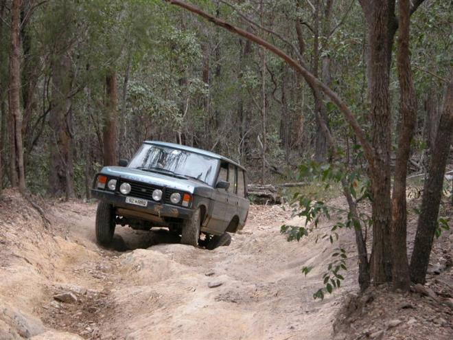
If you are looking at aftermarket suspension you can use the above to determine if what you are doing is of benefit. There is no point in going for longer shocks that 640mm unless you drop the panhard rod a bit, or force the bushes with longer springs. If the compressed length exceeds 400mm, you need to extend the bump-stops. Now I just have to figure out how to flex up like the rear of this Rangie. Rover Flex

HIR Bulbs for High Beam

Being a keen experimenter and open to new ideas, I decided to try the cheaper HIR bulb option in my ’98 100 Series Landcruiser High Beam as opposed to the HID kits. The ’98 Cruiser runs a traditional glass multi segment fresnel lens with two parabolic reflectors. The reflectors are separate for High and low beam with separate bulbs. The later year cruisers have changed to a faceted reflector with a clear polycarbonate unbreakable lens.

The High Beam bulb in my cruiser is a 9005 HB3, Low beam 9006 HB4. These can be swapped with a HIR 9011 bulb that is very similar in design. A small plastic tab needs to have about 3mm of plastic trimmed to fit in the socket.

I purchased mine from www.finemotoring.com in the US who has plenty of information on HIR bulbs. The bulbs arrived in about 10 days, and I found the service prompt and friendly.

HIR bulbs are brighter than conventional Halogen bulbs, including the high output types, and cheaper than HID. I went for them as they are on instantly (HID needs to warm up),  cost effective, simple drop in, no ballast to mount, and I wanted to see what they were like. There is also less legal concerns running these bulbs than HID’s, but I’ll skirt that issue as it seems to be somewhat murky. Headlight and vehicle modification legality debates are contentious at best.

The HIR’s  draw 65w, meaning there is no need to re-wire the car to get a reasonable voltage to them. Running 100W or 130W halogen’s requires re-wiring in most cars. Failing to do this gives a significant voltage drop through the loom, and low voltage at the bulb. Halogen’s hate low voltages very quickly falling in brightness. A 130w bulb underdriven will produce less effective light then a well driven 55W. I have rewired the headlights in several previous vehicles, but am getting lazy in my old age. I haven’t measured terminal voltage to check the amount of loss, but with the engine running and 13.8v at the battery, they seemed fine.

The bulbs that I removed where Silvania 55w units of unknown age. There was no visible material deposited on the glass and the filaments were in good condition, so I would estimate their output to be well within 90% of new. Bulb’s tend to lose output as they age. High beam doesn’t get as much use as low beam, likely contributing to their good condition.

ARB and IPF are flogging HIR as the next best thing, with prices to match. I don’t know where they are sourcing theirs from, and some of their information seems contradictory with other sources on the web. Well, that’s this new intertechnoweb thingymajig for ya.

Fitting was moderately easy. The sockets for the bulbs are tight and tend to hold dirt, with difficult to remove plugs. They are also require removal of the battery to access the sockets, and lifting 35kg of AGM battery out of the tray is great fun.

The outcome is “acceptable”. The light is whiter and brighter, but not hugely so. These are not HID output colour’s or levels. The photo’s don’t give a good comparison as the camera light metering affects what you see. I would estimate the increase to be in the realm of 30 – 50%. Due to the lens design it doesn’t throw the light that much further, maybe 10 or 20m, but the fringe regions are more clearly lit, and the colour is less yellow, probably about 300K whiter at a guess. The centre area’s have more white light in them, but were acceptable before. There is some colour difference when projected onto the garage door, or when you look at them, however the camera doesn’t capture it. They are NOT blue or purple to look at.

I would score them about 6/10 – acceptable as a quick, simple cost effective upgrade with more, but with the falling price of HID kits, I think I’ll just go HID in everything.


Low Beam – Conventional


High Beam – Conventional
(Landcruiser keeps Low Beam lit when High is on)


High Beam – HIR Bulbs

eBay Chinese HID’s and Hella Rallye 4000 Review

I first saw Hella Predator HID’s back in 2000. I *nearly* managed to steal a set from Possum Bourne’s (RIP) support truck in 2001, but the mechanic got suspicious when I borrowed his spanner to work on his truck. It was a good Rally Qld. Unfortunately at $1200+ / piece they were out of my league.

Then along comes 2007, eBay and the advertising below: “UNVEIL THE NOBLE’ SGASEITY, DISPLAY THE KING’ DEMEANOUR” How could I resist? I love dodgy asian translations to advertise stuff. It was the above eye catching statement that made me decide this had to be the best HID offer on eBay. Oh, and it was the cheapest. The guy said he was in Australia, but the excessive postage cost and long delivery time seemed to put some doubt on that fact. The ratings on the account were good, and the product arrived OK, but he did cancel his account 2 weeks later. Dodgy? I’m still not sure. I did order and pay for extra High Tension cables, and had a longer 12v wiring loom supplied instead, but this could be simple mis-communication.  

So I am now the proud owner of some shiny kit to fit the shiny Hella Rallye 4000’s that came with my cruiser. I went with 4300K (the lowest colour temp) bulbs after doing much research across the web. It’s not a pretty purple colour, but far bluer than a normal Halogen. Whilst it might look cool, blue is very hard to actually see anything by, especially in dust or bad weather. That’s why fog lights are yellow, it penetrates more, and reflects less. I know in the rally car, in bad dust, you could see more with the driving lights off. White light reflects badly. Dull yellow headlights work best. 4300K is not yellow at all, but it is very easy to see by in good weather.

These are 35W units, the most common. There are some suppliers out there with 50W units. After testing, I don’t need the 50w units, these are fine. For those that aren’t aware, colour temperature has NOTHING to do with brightness. There is a large range of what people call “white” light. It is measured in degrees Kelvin. It is based on a block of pure carbon being heated in a vacuum. As is gets hotter it starts to glow. The actual temperature of the carbon is used as a reference to the colour it is glowing, from dull red (1500K), to yellow (2000-3000K), white (4300 – 5000K) , blue (6000K) and purple (7000K) as it gets hotter.  I decided to put them into the driving lights for a number of reasons

  1. If they play up it’s no big deal
  2. They take 30secs to warm up – not ideal in normal headlights
  3. I want these for LONG range, and the driving lights are for that purpose
  4. I did always want those Hella Predators


All required equipment and safety gear 🙂

I was not impressed when I pulled the Rallye 4000’s open and found that they were NOT watertight. They are designed to shed water, but there is no ring seal, and no seal near the bulb. The sealed electrical connection at the rear becomes a bit of a waste. So much for the overpriced driving lights. The Lightforce 170’s I put into my brother’s Jeep were far more waterproof than this.  I have had some comments from a friend with one that the reflectors don’t corrode like many lights, even with cracked glass, but I still prefer mine sealed. I was further unimpressed with Hella pricing a replacement lens within $20 of the cost of a whole new light. At $220ea for a light, no clear lens protectors and no reasonable replacement cost, that’s just rude.  I put $40 Lightskinz on mine, having been happy with them before. They don’t collect dirt like normal clear plastic protectors.


 I was rather impressed with the top quality silicon High Tension leads, and the silicon rubber seals on all the electrical connections. Cheap chinese perhaps, but very well presented with a high quality feel.  You can see the standard halogen vs the HID bulb. It looks like they simply change the plastic base for the bulb, and keep the capsule the same. When you buy them you generally have a choice of colour temp and base style to suit you vehicle and preference. The short High Tension leads are a problem. You need to put the igniters/ballast unit close to light, possibly where it will get wet. I would prefer well back in the engine bay. Oh well, have to see how waterproof it really is. Mine is mounted inside the bullbar. You can’t extend these leads easily, as they may carry 6000V+ to fire the bulbs. That needs special connectors and insulation, like your spark plugs.

 
The HID Bulb is slightly wider than the standard glass envelope. This makes it a touch fit in the Rallye 4000’s. I am still concerned about the touch fit becoming a break fit when things get hot, but seems OK so far. Ideally I should file the glass reflector a little with a dremel or something, but can’t be bothered. You can see the silicon sealant Hella uses doesn’t go 360 deg around the socket. The reflector is upside down in this pic. It’s only designed to deflect the water, not handle submersion.

 
Round plug (seal) – Square Hole. Bugger. Oh well, silicon fixes all ills, and it’s out of sight when on the car.

 
There are lots of comments on the web debating how HID’s may not work with normal reflectors due to the light coming from a ball as opposed to a filament, or not being at the focal point. They may be correct, but seems to work OK with these lights, and I suspect with most others. You can see the actual glass ball within the main capsule.

 
HID on the right, standard on the left. You can see the colour comparison. Real colours are hard to capture with a camera as the brightness throws it’s metering out badly. Regard it as comparative as opposed to qualitative.

 
HID on the left. I would estimate at least double the standard brightness, and close to triple. The standard High Beam on the outside looks very poor in comparison.

 
Slightly longer shot. The beam is fuller over a larger area, and far more intense.

 
Now for the acid test. This is standard Landcruiser High Beam. That is a 55w low beam and 60w high beam both operating together.

 
Add HID – presto – we have daylight. Again the camera changes it somewhat, but to get the best idea look at 3 things.

  1. Colour – far whiter light
  2. Distance – You can see the end of the street
  3. Spread – that 1/2 circle is very bright in real life.

I don’t particularly love the spread of the Rallye 4000’s – it’s too narrow. They need another pair of spread beams. That said, I had a single Rallye 4000 spread beam with a 100w Halogen in it, and you couldn’t tell the difference with it on / off to the normal headlights. They need a set of spread beams with them. My plan is to HIR the high beams and HID the low beams. That may give me enough spread light to supplement the spotlights. Once warmed up they stay warm for several minutes, so dipping your lights for passing cars doesn’t mean a significant time without bright lights. It takes about 20 seconds from stone cold to get to full brightness. Even when warming up, they produce light, probably as much as a normal headlight, but you notice the difference compared to the photo above.

Conclusion

Rallye 4000 Spots: I don’t particularly love the spread of the Rallye 4000’s, or their waterproofing. I’m tempted to eBay these and buy Lightforce.  – Not recommended 3/5

Chinese HID’s: I do love the 4300K H1 HID’s. I’ll advise how they go in the long term, but for now – highly recommended. 4/5 until I trust them.

Diff’s for Dummies

Because I got sick of explaining why the diff lock button in your Cruiser / Discovery is not the same as the diff lock buttons in mine…..

https://web.archive.org/web/20060816054148/http://www.safari4x4.com.au/80scool/george_couyant/diffs/diffs.html

Summary: If you own an AWD car – AWD should stand for Any Wheel Drive – Any wheel with the least traction will get all the drive. The centre diff button just turns it into a “normal” “traditional” 4wd, that is one front and one rear must lose traction to stop going forward. This happens on many hills and is the reason pressing this button doesn’t do that much more to where you can go.

Sundown Trip Report May ’07

Road worse than normal, soft roaders would get in but need help to get out.

Plenty of water at Burrows Waterhole – this surprised me. The toilets are getting pretty full, the ranger plans to build new ones.

Red Rock Gorge track in good condition, no problem for soft roaders.

Reedy Creek track in poor condition – similar to Rat’s Castle.

Rat’s Castle road in usual condition. Soft Roaders need not apply. Standard Nissan Pathfinder managed the loop, but be prepared to use plenty of right foot.

“The side road” Mr Robert made so famous with his snapped axles, 10 snatch strap, 4 vehicle recovery is in fair but overgrown condition. I got down and back up OK, but had to drop tyre pressure to 24psi and use full lockers. Lots of flower fluff in the radiator. You really should have a winch to do this road just in case. There are no big steps at the moment, but plenty of very very loose shale. I followed it through to a creek and nice waterfall that was dry. 500M further along there is a steep climb that would be rather nasty and is *supposed* to bring you out to an open gate near the track. I know the gate, but didn’t try the hill as my rear locker chose that moment to blow a seal. There are two side tracks I sw off this one, but didn’t have time to investigate. One is *supposed* to lead to the old mine.

Casualties – sliced a sidewall on my Cooper AT’s. Slice 45mm long repaired by sending away to be vulcanized – $30. Doing the side road without a spare was nerve wracking. Slice was from a rock corner cutting along the sidewall bulge. Normally my sidewalls fail from pinching between rock and rim, so this is a new one for me.

Spoke to the ranger and he said the old road from Rats Castle down to the south end of the park was destroyed in the ’76 floods. Someone tried it this Easter and ended up smashing a diff or similar judging by oil stains found by hikers. Apparently there are 30 – 40 river crossings and it is not passable. Maybe with a few extreme cars w/ 35’s, winches, lockers, shovels and chainsaws it could be opened, but this would be rather frowned upon. Chainsaws being banned and it being a National Park.

Plenty of wildlife. Saw the usual Deer, Grey Kangaroos, Pretty Face Wallabies, Goats and heaps of bird life.

Great place, great food, great people. It was a good trip.


Soft roaders can manage it – but need help. They were happy for me to help with towing the trailer, but not so fussed on letting us sleep in it….


Rats Castle circuit is a little rough


OME articulates better than I thought

 
Burrows still has plenty of (cold) water

 
This is a view most won’t see of “the hill”. Bring Lockers, and a winch, and axles for any Discovery’s in your party.

Fullriver 120Ah AGM into 100 Series Cruiser

The batteries in the HZJ105 were cactus. They were the ones it came with and the whole system was dubious and time for an upgrade. When I purchased the car the wiring was a mess, although quite effective. I am still sorting some of it out.

My goals were as follows:

  1. Seperate battery for starting
  2. Maximum capacity for Aux items
  3. 80Ah Useable Capacity
  4. Option to expand to triple battery setup for winching

I’ll go into a debate on battery system choices in a seperate article, but to meet my needs I chose the following:

Odyssey PC925 – Small Start Only battery
These small expensive AGM’s are made to deliver spectacularly high starting currents from a small battery. If you don’t have room for a Dual Battery setup, or want to go to a Triple setup, then one of these should be your start battery. 925A for 5 secs, 620A for 10 secs – it starts my 1HZ with ease. I’ll update after a -5 winter day, but for the moment it works fine. I didn’t want a huge start battery that never used more than 5% of it’s capacity and wanted to be able to go to a triple setup later.

Fullriver HGL-120 – Aux Battery
These chinese AGM’s seem to be getting great reviews. Ultra low internal resistance means fast charging. AGM commentries are all over the web. The main things that are important to me are:

  1. Fast Charge
  2. Good resistance to deeper discharges
  3. Great vibration resistance.
  4. Adequate Capacity – 80Ah is easily acheiveable from a 120 rated batt

You’ll find out why the AGM costs so much and has higher capacity when you try to lift it. 35Kg as opposed to a conventional N70ZZ at 21 – 25Kg.

Piranha 150A Isolator – Conventional Voltage Sensing Isolator
It came with the car and after bodgy repairs to the cracked plastic case and corroded PCB tracks, now works fine.

Fitting the batteries

The Fullriver comes with an unusual terminal – basically a recessed nut and supplied bolt. You can either take off your conventional terminal and use theirs, or do as I did. Cut the lead terminals off your deceased battery, drill them to fit the bolt though – presto – conventional terminals in case you need to swap back for some reason.

To fit in the landcrusier cradle you’ll need to remove the plastic tray underneath. It’s not big enough and makes the battery sit up too high. I can’t see any reason for it’s existance, as the paint underneath is rubbed anyway, and it doesn’t have a drain making acid protection pointless.

You’ll also need to modify the rear “hook” bracket. It is too short and wont go over the slightly taller battery. 2 minutes with an turbo torch had it red hot and rebent. There is enough length in the bent peice hook to straighten and rebend it as a longer straight shaft.


Odyssey TEMPORARILY mounted in original position. This one battery replaced 2 batteries triple it’s size. Plan is to put it in the rear of the engine bay on a small tray. No need to move fuel filters and less weight.


Clearances are tight, but it fits. Modified terminals can be seen.


Modified rear hook mount needed for additional height. You can see the tight clearances.

Comments:

Conventional Wet cells don’t have enough useable capacity for my demands. Deep cycled they die.

Conventional Deep Cycle cells are slow charging. I doubt I’ll have the engine running for long enough to charge them fully.

I have concerns about AGM’s and heat. All Lead Acid cells have a positive feedback cycle when charging. ie, the hotter they get, the more current they adsorb, making them hotter, making them adsorb more current……
Normal wet cells will outgas if this gets out of hand, and you get to top them up with water. AGM’s recombine the gases, releasing more heat. This can be bad. 50deg is the theoretical max, but that is also said for conventional cells. Most people get away with it, some don’t .Ideally, mount them inside the vehicle. Personally, I’m going to put an aluminium heat shield in to keep the worst of the radiator heat from blowing on them, and rely on their forward position to feed them cool air. Some people do nothing and have no worries. Others have problems.

The isolator – like 90% on the market simply parallels the cells when the input voltage hits 13.6v. Many claim all sorts of wizardry, most are simply relays in a black box. 

Batteries lead an isolated life

Battery isolators and battery systems are always an area of hot debate. This article is not to get into the differing battery constructions and variants, but rather into the systems to manage them.

In an ideal world every cell would be managed independently, and batteries would cover all our needs. The reality is that we have to make do with  differing solutions and varied information.

Some of the best battery information is here, here and here

This guy also has great information.

The general rule is that deep discharges shorten a Lead Acid batteries life. Cells not built for this are damaged very quickly. My experience has been that an average brand name 12mth old battery flattened by headlights overnight is basically stuffed and won’t carry more than 30% of it’s new capacity. It’ll start the car fine with this shallow charge, but that’s it.

The goal of an isolator system should be to
a) Leave you able to start the car
b) Minimise deep discharges of any battery

Now we come to the point of most arguments discussions. In most cases people opt for separate batteries, one for starting and one for auxiliary use. This means that the requirements the batteries face are not the same, and often differing batteries are chosen for these tasks. Further, as they are subjected to differing conditions they age independently and often will be replaced at different times. Yet the manual that your isolator came with, your mate on the Internet, and quite a few battery manufacturers will be telling you “DO NOT PARALLEL BATTERIES OF DIFFERENT CONSTRUCTION / SIZE / AGES”. That’s it. The discussion never moves beyond that point. There are HUGE debates on forums all over the Internet, yet they can’t get beyond this point. Series string construction and management is discussed ad-nauseam, yet the classic 4wd warning remains. Luckily for us, they are WRONG.

Evidence, More Evidence, even More Evidence

Parallel what the hell you like, it won’t matter. Which is lucky, because MOST expensive battery isolators do just that, and have for years. They all claim to be magic in a box, but most are relays, something known about for a little while now and use in all sorts of places.

Battery Calcs & Types

The calculations below are based on what I phrase “effective capacity”. This varies depending on battery type and it’s use. I’m going to assume you have it in a 4wd and drive a 2 – 4 hours a day when on trips. The numbers below are based on not wanting to flatten the battery more than 80% and it’s likely state of recharge from a normal alternator (your mileage may vary). You can roughly work out your effective capacity as follows.

  1. Starter Battery
    (0.4 * RC) * 0.8
    =approx 48Ah for N70ZZ batt
  2. Deep Cycle
    Ah * 0.5
    =approx 50Ah for 100Ah batt due to common low state of charging.
    This *may* be better if there are very long charge times or high charge voltages.
  3. AGM
    Ah * 0.8
    =approx 80Ah for 100Ah batt due to fast charge capability.

Remember – these are for NEW batteries – it only gets worse as they age. Ageing depends on time, temperature, cycles and depth of discharge.

Isolator System Types

  1. Parallel / Single Battery
    Works well enough, if you don’t discharge it too far. If you do discharge it you’ll be stuck looking for a jump start. Auto cut out devices and voltage monitors are a good solution. It’s also the cheapest up front solution – no parts needed. You’ll not be game to discharge your batt’s below 70% effective capacity if you want to start the car, so your capacity is:
    0.7
    * “effective Ah rating of battery type”
    * 2
    =Useable AH
  2. Diode Isolator
    These are generally regarded as inefficient. Jaycar has one here. They induce a 0.6v drop across them. According to Odyssey this is the difference between fully charged and 50%. What will happen is charge voltages are high enough that losing 0.6v means the battery will charge 30% – 50% more slowly than normal, and possibly not charge fully. Theoretically a solid state MOSFET solution would work well, but I haven’t seen one yet. Relays are cheaper I guess. You only get one battery so the rough calculation is:
    AH = 0.7 * “effective Ah rating of Aux Batt Type Only and a slow charge”
  3. Voltage Regulated Isolator
    This is the most common solution. Redarc is the most obvious (no box), but Piranha’s black box of tricks is the same thing. My black box fell to bits and inside it’s just relays connecting the batteries. They work by isolating the batteries when the voltage drops below a set point – around 13v. When the primary battery is back above 13v due to the engine running, it reconnects them. They generally should build in a bit of hysteresis (damping) to stop is short cycling if the voltage is close to the cutoff. The calculation is:
    AH = “Effective Ah rating of Aux Batt Type”
  4. VR Isolated with Lower Cutout than Cut-in.
    Traxide does this really cool VR Relay isolator. By setting the cutout to the mid 12v, it lets you use 50% of your primary battery. Normally in an isolated system there is this huge heavy main battery there for just starting. I find this a waste. If I can use 50% of it’s capacity safely, then I would prefer to do so. The calculation for this system is:
    AH = (“Effective Ah rating” (Aux)) + (0.5*”Effective Ah rating” (Main))
  5. Independent Management
    Now we get to the tricky (read expensive) stuff. To fully manage all batteries to their maximum potential all batteries (and ideally cells) need independent attention. People that live on solar or independent power often take inordinate care of their batteries, or alternately buy batteries that last 50 years. For 4wd use this means independent charging. There are a number of ways this can be achieved from vendors such as RotronicsAmplepower and Arrid. Temperature compensation is one of the most important components, but they also regulate charge voltage, pulsation, float test etc etc. Nice stuff, but be prepared to pay for it. It may be cheaper for the casual user just to put new batteries in every 2 – 3 years, but if you live off it, then your use would probably justify the extended service life.

Personally I work out the following.

Battery & Isolator Cost and Capacity Calculator Spreadsheet

My Waeco CF50 uses *about* 3A @ 50% duty cycle * 24Hrs = 36Ah/day.
Add a couple of 8w flouro’s (1.5A * 3Hrs) and maybe the radio = about 45Ah / day.
I often want to stay 2 nights in the one spot, so I want nearly 2 days supply.
80 – 100Ah is enough for what I need.
The cheapest system that can deliver that is a Normal Start Battery + an AGM with a Traxide isolator.

There is a spreadsheet attached here that works out approximate the economics and capacities of each system. If you have unusual requirements or conditions, then the numbers will have to be tweaked a bit.

Interestingly the cheapest setup that also gives the most Ah/$ is simply a pair of normal Start batteries in Parallel. Unfortunately 67Ah useable is not enough capacity for my needs. $4.50/Ah

The most cost effective for my requirements is a normal Start battery + an AGM with a “Tricky Voltage Relay” by Traxide. 104Ah and $5.30/Ah

The very common Isolator + Deep Cycle solution works out to about $11.0/Ah – not very cost effective.